
Lee on Toteable PC Is Inspired By Macs Of Days Gone By.João Paulo Ferreira Claro on A Cassette Interface For A 6502 Breadboard Computer, Kansas City-Style.

#SDR DIY ANTENNA HOW TO#

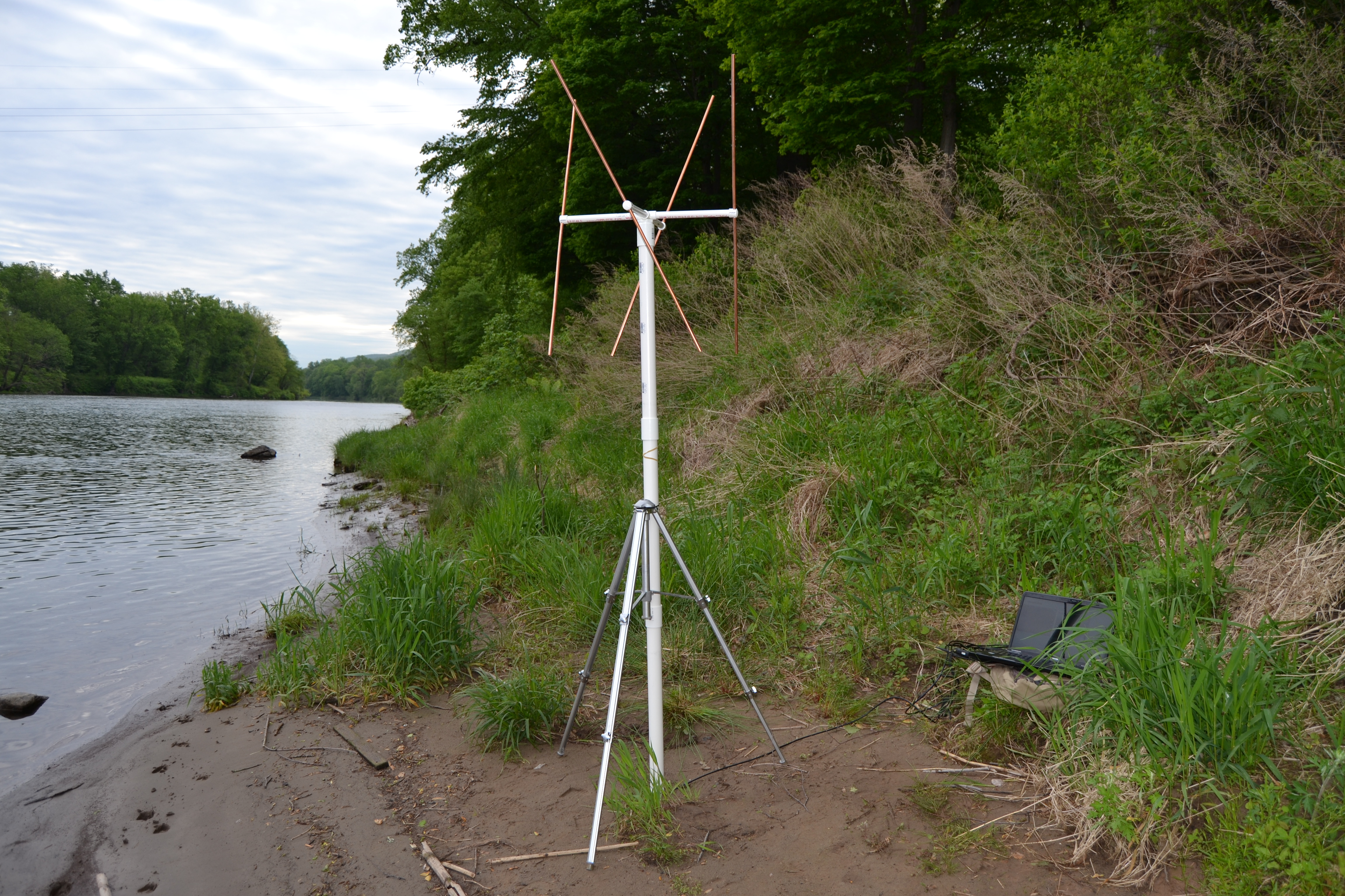
Posted in Radio Hacks Tagged antenna, RTLSDR, sdr Post navigation Or, just bite the bullet and build something that looks like it belongs in a movie. If you want to do before and after testing, we’d suggest using Python. On the other hand, the magnetic base and reasonably small form factor is pretty attractive. You might get more mileage out of that approach. We actually have simply cut these antennas off and reused the cable and connector to hook up a better antenna. We also thought about the goop you use on tool handles. A nice 3D printed housing would work, too, and might improve the appearance. You could probably come up with something nicer to reseal the base, but the tape does work. The result might be called an ugly duckling rather than a rubber ducky. He fixed both of these problems, as you can see in the video below. The second problem is there’s no real ground. You’d like to have enough to pull out a quarter wavelength on the longest frequency you want to operate. power amplifier (PA).Knows there are at least two things wrong with the cheap antennas you get with most SDR dongles. This signal can be used also by other equipment connected to the TRX e.g. Further on we will refer to it as TRX PTT. This signal has different names from transceiver manufacturers: SEND TX-GND T/R-LINE Ground-on-Transmit. * A standard “TX transmits” output from the TRX is used as a control signal.
#SDR DIY ANTENNA FULL#
This protection can withstand full TRX power. There is a high power input RF limiter for high currents keeping the input voltage of the SDR at safe levels.

The smooth and regulated delay to switch back the SDR audio at proper time avoids the disturbances from delayed signal from the SDR. SDR audio is muted during transmission and side tone is from the transceiver.While listening with your transceiver the transmit antenna is not disconnected from the SDR and the spectrum display on the PC is active.The SDR frequencies and modes are synchronized with your transceiver (with any popular SDR software) and with a simple mouse click you can go quickly to any frequency on the band. With this T/R switch you can integrate your transceiver and SDR and have similar or better receive performance than a high grade state of the art transceiver.


 0 kommentar(er)
